The Phase-II Level-0 (L0) muon trigger system in the barrel region selects muon candidates with pT > 20 GeV for single-muon triggers, with pT > 10 GeV for di-muon triggers and with pT > 4 GeV for topological and multi-object triggers. The L0 muon (Barrel + Endcap) output rate for 20 GeV single-lepton is ~40 kHz, while the output rate for 20 GeV single-lepton in the barrel is ~30 kHz.
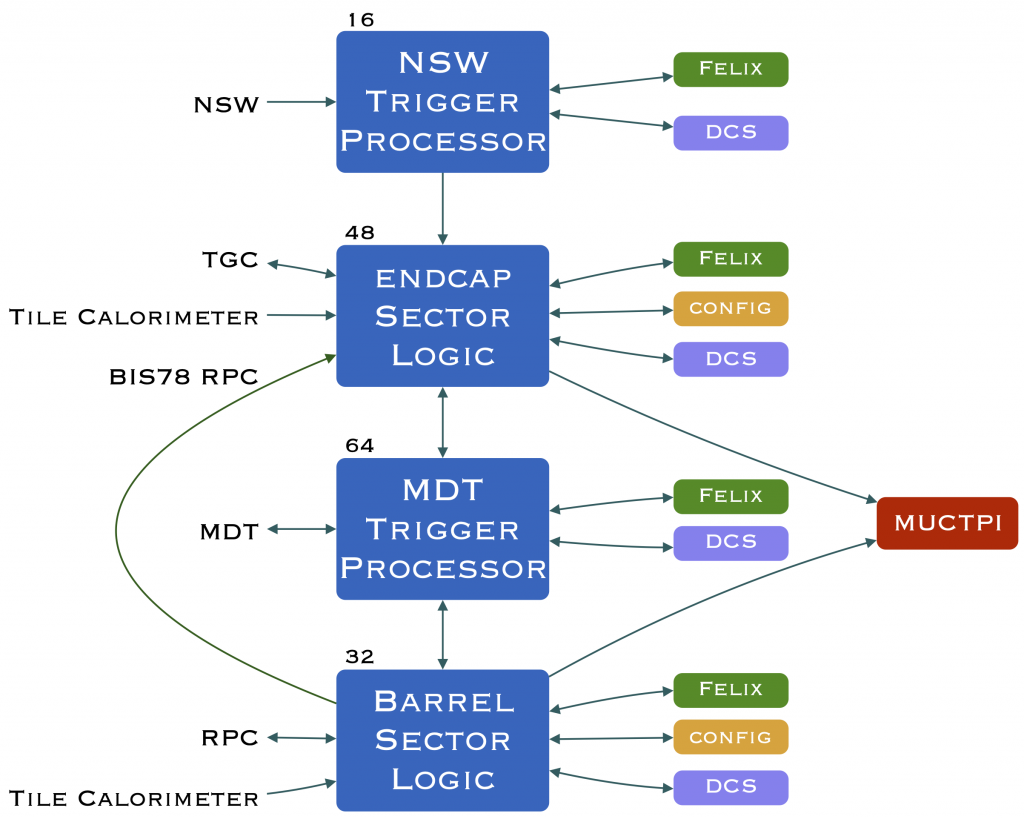
The L0 muon trigger algorithm is executed by 32 ATCA boards in the barrel region and 48 boards in the endcap region. These boards are called Sector Logic (SL) boards and are located in the Underground Service ATLAS (USA15) experimental hall. The SL is an FPGA based board which receives detector data, performs the L0 algorithm and sends its muon trigger candidate information to the Muon Central Trigger Processor Interface (MUCTPI) board, also located in USA15.
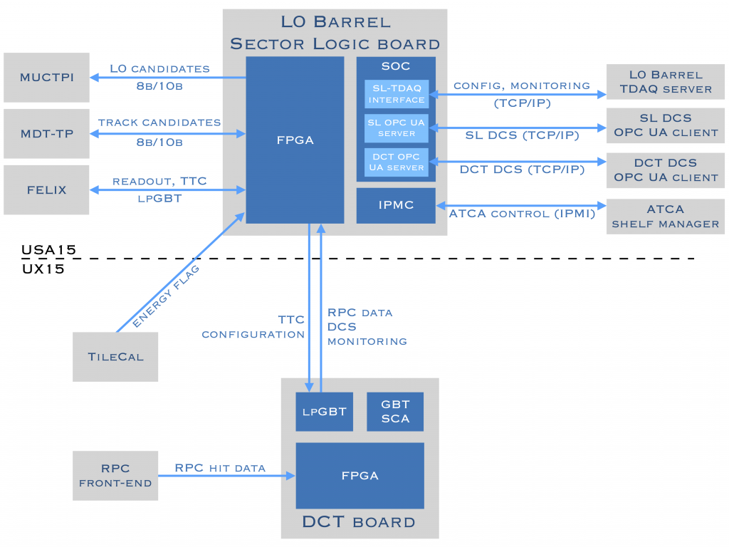
The Resistive Plate Chamber (RPC) and Tile Calorimeter detectors full-granularity hit data are digitised on-detector and sent to the barrel SL boards on optical fibres [1].
The SL also communicates with the Monitored Drift Tubes (MDT) Trigger Processor (MDTTP) board, to which it sends the muon candidate geometrical coordinates and trigger threshold measurement. The MDTTP reconstructs the muon candidate track in the MDT region identified by the SL and sends the candidate pT back to the SL with a higher precision. In the case the MDTTP reconstruction algorithm is not satisfied the candidate is flagged as not reconstructed and rejected by the SL. The MDTTP selection algorithm reduces the RPC rate from ~85 kHz to ~30 kHz (see 6.4, “L0”, [3]). The SL finally sends the selected L0 muon candidates information to the MUCTPI.
The Phase-II L0 muon trigger system in the barrel region makes use of the RPC and Tile Calorimeter hit-data to select muon candidates applying a multi-layer coincidence based algorithm. The on-detector Data Collector Transmitter (DCT) board samples the RPC hit-data and sends it to the barrel SL with zero suppression. Two DCT boards are installed on each RPC station in the Barrel Outer (BO) region, four in the Barrel Middle (BM) region, one or two in the Barrel Inner (BI) region. The full barrel on-detector trigger electronics is made of 1572 DCTs. The DCT zero suppression logic allows to minimise the data to be sent to the SL, but requires local buffers to keep the data in the DCT during processing and transmission. VHDL simulations have been performed to assure that all RPC data are transmitted to the SL within the required DCT latency. The SL shall compensate the different DCT latency time event by event to guarantee a fixed latency transmission from the SL on, using the Bunch Crossing (BC) number sent by the DCT together with the RPC data.
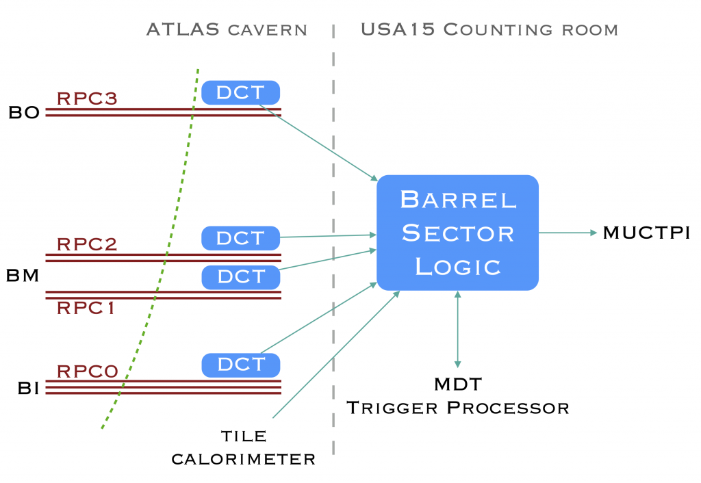
L0 Barrel Muon Trigger system schema. Max 51 DCT boards are installed per every barrel sector.
The figure above shows the L0 Barrel Trigger system schema. One BI RPC station is made of a triple gas gap RPC chamber, a BM station of two double gas gap RPC, the BO region of one double gas gap RPC. One ATLAS sector has up to 51 DCT boards (BI+BM+BO), connected to one SL board. The full L0 barrel system has 32 SL boards, one per each ATLAS sector. The SL elaborates the RPC geometrical coordinates of the muon candidates and sends them to the MDTTP, which sends back a confirmation or rejection decision. The final selected candidate is sent to the MUCTPI.
L0 Barrel Muon Trigger system schema. Max 51 DCT boards are installed per every barrel sector.